Quantcast
Channel: VMware Arena
Viewing all 326 articles
Browse latest View live

VMware NSX Installation Part 7 – Verify NSX VIBs Installation from ESXi hosts

$
0
0

In the previous post, we have discussed about preparing cluster and hosts for NSX. Once the installation is completed, The installation status will change with the Green Check Mark along with the NSX Version of code (6.1.0) running in the cluster along with Enabled Status for Firewall. Let us verify the NSX installation from ESXi host and what are the changes made to esxi host after the Host preparation. Successful host preparation on the cluster will do the following:

  1. Install network fabric VIBs (host kernel components) on esx hosts in the cluster.
  2. Configure host messaging channel for communication with NSX manager.Installs User World Agents (UWA).
  3. Make hosts ready for Distributed Firewall, VXLAN &  Distributed Router configuration.

Verify NSX Installation from ESXi host _7

Verify  NSX User World Agent (UWA) Status:

The user world agent (UWA) is composed of the netcpad and vsfwd daemons on the ESXi host. UWA Uses SSL to communicate with NSX Controller on the control plane. UWA Mediates between NSX Controller and the hypervisor kernel modules,except the distributed firewall. Communication related to NSX between the NSX Manager instance or the NSX Controller instances and the ESXi host happen through the UWA. UWA Retrieves information from NSX Manager through the message bus
agent.

we can verify the status of User World agents (UWA) from CLI:

/etc/init.d/netcpad status

Verify NSX Installation from ESXi host _1

From the ESXtop, You can verify the Deamon called netcpa running:

Verify NSX Installation from ESXi host _2

User World Agents (UWA) maintain the logs at /var/log/netcpa.log

Verify NSX Installation from ESXi host _3

Verify Installation Status of NSX VIBs:

Below are the 3 NSX VIBs that get installed on the ESXi host:

  1. esx-vxlan
  2. esx-vsip
  3. esx-dvfilter-switch-security

Let’s verify that the all the above VIBs are installed using the below command

esxcli software vib get –vibname esx-vxlan

Verify NSX Installation from ESXi host _4

esxcli software vib get –vibname esx-dvfilter-switch-security

Verify NSX Installation from ESXi host _5

esxcli software vib get –vibname esx-vsip 

Verify NSX Installation from ESXi host _6

That’s it. We have verified the status of NSX ViBs installation on ESXi hosts. In the upcoming post, We will take look at configuring VXLAN. I hope this is informative for you. Thanks for reading!!!. Be Social and share it in social media, if feel worth sharing it.


VMware NSX Installation Part 8 – Configuring VXLAN on the ESXi Hosts

$
0
0

Once Cluster preparation is completed, It time to configure the VXLAN. Virtual Extensible LAN (VXLAN) enables you to create a logical network for your virtual machines across different networks. You can create a layer 2 network on top of your layer 3 networks. VXLAN transport networks deploy a VMkernel interface for VXLAN on each host. This is the interface that will encapsulate network segments packets if it needs to reach a guest on another host. By encapsulating via a VMkernel interface the workload is totally unaware of this process occurring. As far as the workload is concerned the two guests are adjacent on the same segment when infact they could be spanning many L3 boundaries.

To configure the VXLAN, Login to the Web Client > Networking & Security > Installation > Host Preparation-> Configure .  A wizard will ask for VXLAN networking configuration details. This will create a new VMkernel port on each host in the cluster as the VXLAN Tunnel Endpoint (VTEP).

VMware NSX -VXLAN Configuration -4

Provide the below options to configure the VTEP VMkernel Port:

  • Switch – Select the DvSwitch from the drop-down for attaching the new VXLAN VMkernel interface.
  • VLAN – Enter the VLAN ID to use for VXLAN VMkernel interface. Enter “0″ if you’re not using a VLAN, which will pass along untagged traffic.
  • MTU – The recommended minimum value of MTU is 1600, which allows for the overhead incurred by VXLAN encapsulation. It must be greater than 1550 and the underlying network must support the increased value. Ensure your distributed vSwitch (DSwitch) set MTU size more than 1600.
  • VMKNic IP Addressing –  You can specify either IP Pool or DHCP for IP addressing. I don’t have DHCP in my environment. Select “New IP Pool” to create a new one same as we created during NSX controller deployment. I have used a IP pool called “ VXLAN Pool”

VMware NSX -VXLAN Configuration -5

Enter the IP Pool Name, Gateway, Prefix Length, Primary DNS,DNS Suffix and Static IP Pool range for this New IP Pool and click on Ok to create the New IP Pool.

VMware NSX -VXLAN Configuration -6

  • VMKNic Teaming Policy – This option is define the temaing policy used for bonding the vmnics (physical NICs) for use with the VTEP port group. I have left with the default Teaming policy “Static EtherChannel”
  • VTEP  – I left the default one and it is not even allowed to configure ,if you choose “Static EtherChannel” as your Teaming policy.

Click on Ok to create the new VXLAN vmkernel interface in the ESXi hosts.

VMware NSX -VXLAN Configuration -7

Once the VXLAN is configured, You will be able to see the status of the VXLAN is changed to “Enabled” for that particular cluster.

VMware NSX -VXLAN Configuration -8

As discussed in previous steps, Configure the VXLAN for other clusters in your vCenter.

VMware NSX -VXLAN Configuration -9

VMware NSX -VXLAN Configuration -10 Both of my compute clusters are configured with VXLAN and VXLAN status turned to “Enabled”.

VMware NSX -VXLAN Configuration -11

You can notice the VXLAN VMkernel interface is created for the ESXi  hosts in the Compute clusters. It assigns the IP address for the VXLAN VMKernel interface from the IP Pool which we have created earlier.

VMware NSX -VXLAN Configuration -12


VMware NSX -VXLAN Configuration -13

You can verify the same from the  Networking & Security > Installation > Logical Network Preparation>VXLAN Transport.

VMware NSX -VXLAN Configuration -14

 
We are done with configuring VXLAN for ESXi hosts. We will configure Segment ID and transport Zones in the upcoming posts. I hope this is informative for you. Thanks for Reading!!!. Be Social and share it in social media, if you feel worth sharing it.

VMware NSX Installation Part 9 -Create Segment ID and Transport Zones

$
0
0

In the Previous post, We have discussed about configuring VXLAN on ESXi hosts. We will discuss about creating Segment Id and transport Zones in this post. You must specify a segment ID pool for each NSX Manager to isolate your network traffic.

Segment ID:

Segment ID range carves up the large range of VXLANs available for assignment to logical segments. If you have multiple NSX domains or regions you can assign a subset of the larger pool. Segment ID pools are subsequently used by logical segments for the VXLAN Network Identifier (VNI).  Create Segment ID by Login to Web CLient ->Networking & Security -> Installation -> Logical Network Preparation -> Segment ID ->Click on Edit

VMware NSX -VXLAN Configuration -15

The segment ID range determines the maximum number of logical switches that can be created in your infrastructure. Segment ID is like VLANs for VXLAN but with VXLAN, you can have 16,777,216 of them and VLAN is only limited from 1 to 4094. Segment IDs will form the basis for how you segment traffic within the virtualized network.It is possible to use values between 1 and 16 billion, VMware has decided to start the count at 5000 to avoid any confusion between a VLAN ID (ranges from 1 to 4094) and a VXLAN Segment ID. So your VXLAN ID starts from 5000. Here I use the segment range of 5000-10000. Click on OK.

VMware NSX -VXLAN Configuration -16

VMware NSX -VXLAN Configuration -17Transport Zones:

A transport zone is created to delineate the width of the VXLAN/VTEP replication scope and control plane. This can span one or more vSphere clusters. A NSX environment can contain one or more transport zones based on the requirements.In simple terms, Global trasnport Zone is the boundary for group of clusters. Whatever logical switches you create and assign to the Global transport will become available as Distributed Port Group on your DvSwitch on every single cluster in the transport Zone. So these DVPort groups can be used to provide connectivity Virtual Machines which are attached to it. It’s a way to define which clusters of hosts will be able to see and participate in the virtual network that is being defined and configured.

To create Transport Zone -> Login to Web Client ->Networking & Security -> Installation -> Logical Network Preparation -> Transport Zones ->Click on +

VMware NSX -VXLAN Configuration -18

Provide the Below information to create the New Transport Zone:

Name – Provide the name for your transport Zone. I named as “VXLAN-Global-Transport”

Description – Enter Description as per your wish

Replication Mode – This option enables you to choose one replication method that VXLAN will use to distribute information across the control plane. Here are the detailed explanation about each replication mode from VMware:

  1. Multicast: Multicast IP addresses on physical network is used for the control plane. This mode is recommended only when you are upgrading from older VXLAN deployments. Multicast mode requires IGMP for a layer 2 topology and multicast routing for L3 topology
  2. Unicast : The VXLAN control plane is handled by an NSX controller. All unicast traffic leverages headend replication. No multicast IP addresses or special network configuration is required.
  3. Hybrid : Hybrid mode is local replication that is offloaded to the physical network and remote replication through unicast. This is also called as optimized unicast mode.  This requires IGMP snooping on the first-hop switch, but does not require PIM. First hop switch handles traffic replication for the subnet.

Clusters – Select the Clusters which you want to be part of this transport zone.

VMware NSX -VXLAN Configuration -19

Click on OK to create the Transport Zones. You will be able to see the created Trasnport Zone “VXLAN-Global-Transport” under the Transport Zones. We didn’t created any logical switches , so it displays value “0″ under Logical switches tab.

VMware NSX -VXLAN Configuration -20We are done with creating Segment ID and Transport Zone. Next will be creating Logical Switches and attach it to virtual machines to enable the network communication. I hope this is informative for you. Thanks for Reading!!. Be Social and share it in Social media, if you feel worth sharing it.


VMware NSX Installation Part 10 – Create NSX Logical Switch

$
0
0

A cloud deployment or a virtual data center has a variety of applications across multiple tenants. These applications and tenants require isolation from each other for security, fault isolation, and avoiding overlapping IP addressing issues. The NSX logical switch creates logical broadcast domains or segments to which an application or tenant virtual machine can be logically wired. The logical switch is nothing but a distributed port group on the distributed switch. The logical switch can expand distributed switches by being associated with a port group in each distributed switch.The NSX controller is the central control point for all logical switches within a network and maintains information of all virtual machines, hosts, logical switches, and VXLANs. A logical switch is mapped to a unique VXLAN, which encapsulates the virtual machine traffic and carries it over the physical IP network.

Below is my Lab topology for Logical Switching. I am going to create a Logical switch called “Web-Tier” and attach the 2 Virtual Machines “Web-Svr-1″ & “Web-Svr-2″ into the created logical switch. This Logical Switch will allow the communication between these 2 Virtual Machines in different cluster without having actual physical subnet configured at Physical network layer. For both VM’s , configured IP address is in “172.16.10.x” network and ESXi hosts are in the subnet “192.168.10.x”.

VMware NSX-Logical Switch Creation -1Create Logical Switch:

To create the logical Switch , Login to Web Client ->Networking & Security -> Logical Switches -> + symbol to add new logical switch

VMware NSX-Logical Switch Creation -2

Provide the Name and Description for New Logical Switch. Select the Transport Zone which we have created in the previous step. Select the replication mode as same which you have configured for “VXLAN-Global-Transport” Transport Zone. I have selected “Unicast” mode. Click on Ok to create the new logical switch.

VMware NSX-Logical Switch Creation -3 New Logical Switch called “Web-Tier” is created. Which is assigned with VNI number “5000″.

VMware NSX-Logical Switch Creation -4

As we Discussed earlier, Logical switch is nothing but a Distributed Port Group in your DvSwitches. When you create a Logical Switch, It will create DvPortgroup in all the associated dvSwitches which are part of the Clusters connected in the Global Transport Zone. So I have created a Logical Switch Called “Web-Tier”. I can see the PortGroups “VXW-dvs-53-virtualwire-2-sid-5000-web-Tier” is created in my both distributed switches.

VMware NSX-Logical Switch Creation -4Associate Virtual Machines to Logical Switch:

Once Logical switches are created, We need to associate the workloads (Virtual machines) with the logical switch created in the previous steps. Click on VM symbol to associate the virtual machines to this Logical Switch “Web-Tier”

VMware NSX-Logical Switch Creation -4-1

Select the Virtual Machines from the list to associate with this logical switch (Web-Tier). I have associated the above 2 VM’s from different cluster  into this logical switch. Click on Next.

VMware NSX-Logical Switch Creation -5

For Multi-Nic VM’s, You can even select the specific vNic to connect to this Logical Switch (Web-Tier). My both VM’s are having only 1 vNic. Select the vNics and Click on Next.

VMware NSX-Logical Switch Creation -6

Review the Settings selected and Click on Finish.

VMware NSX-Logical Switch Creation -7

 Simple Ping Test to prove the NSX Logical Switching:

Web-svr-1 – 172.168.10.11 (esxi-comp-01)

Web-svr-2 -172.16.10.12 (esxi-comp-02)

VMware NSX-Logical Switch Creation -9

My ping to the VM “Web-svr-2” (172.16.10.12) from the VM “web-svr-1” (172.169.10.11) is success and I am receiving the ICMP reply for the ping request. This both VM’s are running in different hosts/Clusters but still my ping between the VM’s on the same logical switch is working well with the help of VXLAN.

VMware NSX-Logical Switch Creation -10

When “web-svr-1″ communicates to “web-svr-2″, it communicates over VXLAN transport network. When the  VM communicates and the switch looks up the MAC address of Web-svr-2. the host is aware in its ARP/MAC/VTEP tables pushed to it by the NSX Controller where this VM resides. It is forwarded out into the VXLAN transport network. It is encapsulated within a VXLAN header and routed to the destination host based on the knowledge of the source host. Upon reaching the destination host the VXLAN header is stripped of and the preserved internal IP packet and frame continues to the host.

That’s it. We are done with Logical Switching. I hope you are clear with the concepts of NSX Logical Switch. We will discuss about Distributed Logical routing in upcoming posts. I hope this is informative for you. Thanks for Reading!!!. Be Social and share it in social media, if you feel worth sharing it.

VMware NSX Installation Part 11 – Creating Distributed Logical Router

$
0
0

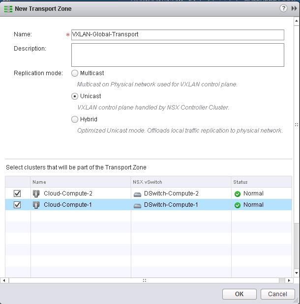
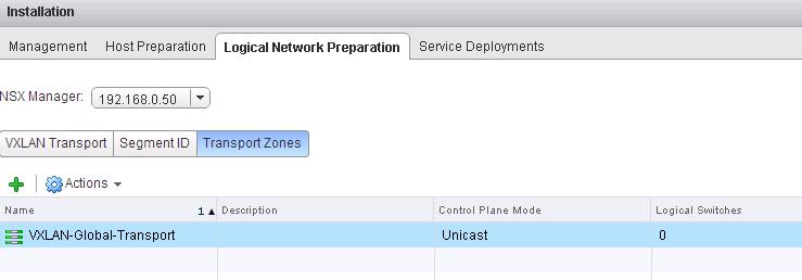
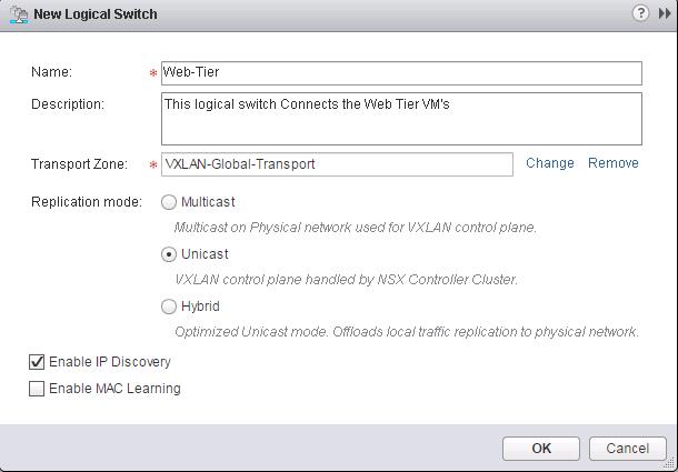
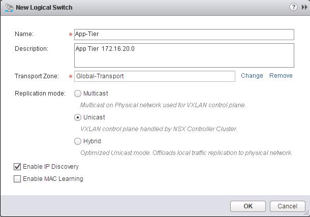
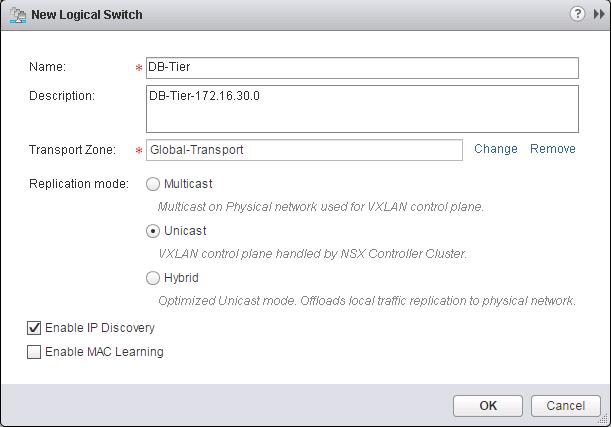
In the Previous post, We have discussed about creating NSX logical switches and now workloads have L2 adjacency across IP subnets with the help of VXLAN. In this post, we are going to enable routing between multiple Logical switches. So We will build three-tier application with logical isolation provided by network segments. Before We deploy the Distributed Logical router, Let’s create additional logical switches. We have already created a Logical switch called “Web-Tier” in the previous post. Now i am going to create two additional Logical switches called “App-Tier” and “DB-Tier”.

I have created additional logical Switches like (App Tier, DB tier along with Web-Tier). We are going to utilize these Logical switches to enable communicate between them using Distributed Logical Routing in upcoming Section

VMware NSX- Logical Routing-1

VMware NSX- Logical Routing-2

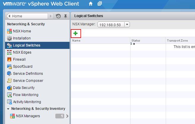
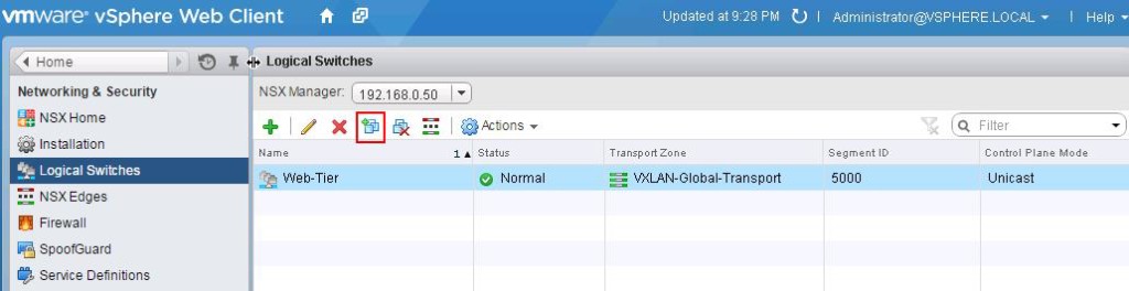
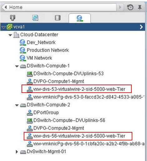
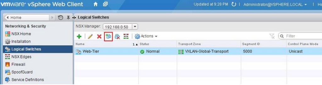
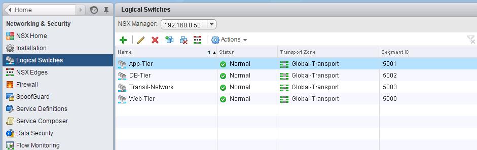
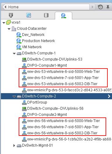
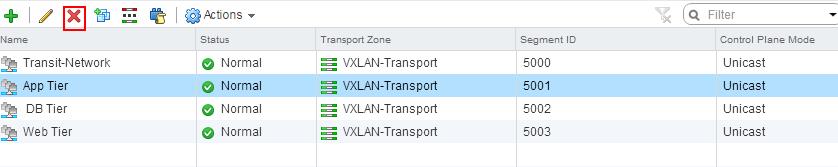
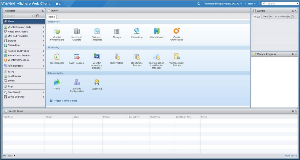
You can see the list of Logical switches which are created from Web Client -> Network & Security -> Logical SwitchesVMware NSX- Logical Routing-3
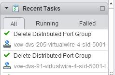
When we create the logical switches, it will create a Distributed Port group on all the respective Distributed Switches.

VMware NSX- Logical Routing-4

Deploying  NSX Distributed Logical Router (DLR):

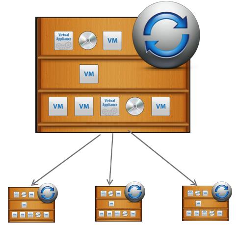
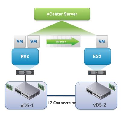
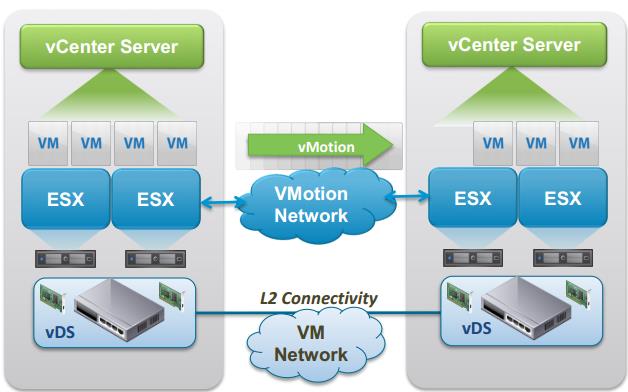
NSX for vSphere provides L3 routing without leaving the hypervisor Known as the Logical Distributed Router. This advancement sees routing occur within the kernel of each host allowing the routing data plane distributed across the NSX enabled domain. The distributed routing capability in the NSX platform provides an optimized and scalable way of handling East – West traffic within a data center. East-West traffic is a communication between virtual machine or a resource within the datacenter.

In a typical vSphere network model, virtual machines running on a hypervisor want to communicate to the VM connected to different subnets, the communication between these VM’s has to go via Physical Adapter of the ESXi host to Switch and also Physical router is used to provide routing services.  Virtual machine communication has to go out to the physical router and get back in to the server after routing decision. This un-optimal traffic flow is sometimes called as “hair pinning”.The distributed routing on the NSX platform prevents the “hair-pinning” by providing hypervisor level routing functionality. Each hypervisor has a routing kernel module that performs routing between the logical interfaces (LIFs) defined on that distributed router instance. LIFs is nothing but the interfaces on the router which connects various networks i.e various Logical switches.

Logical Router can support a large number of LIFs up to 1000 per Logical Distributed Router. This along with the support of dynamic routing protocols such as BGP and OSPF allows for scalable routing topologies.  LDR allows for heavy optimization of east – west traffic flows and improves application and network architectures.

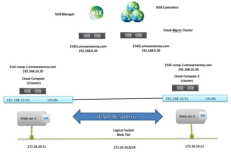
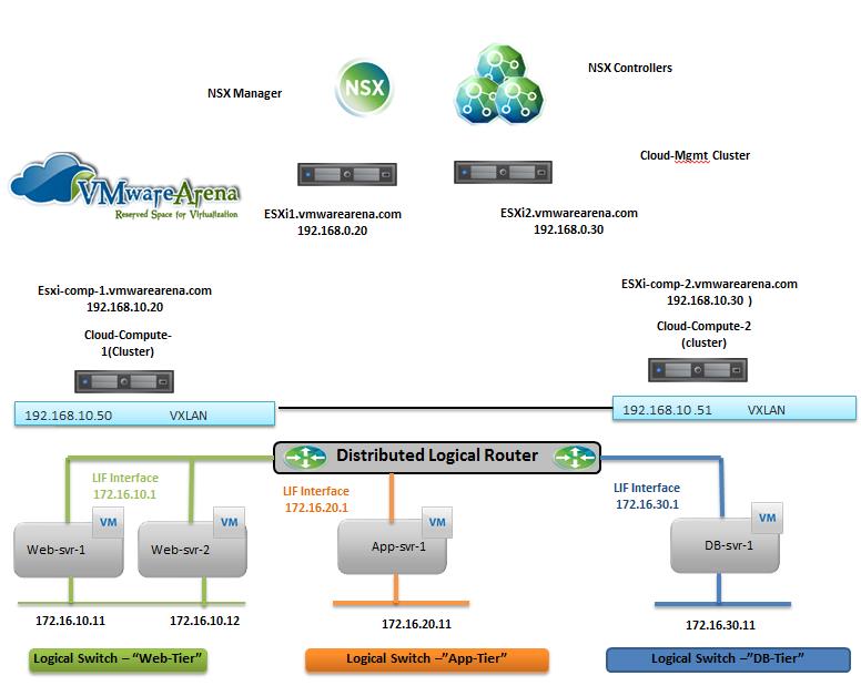
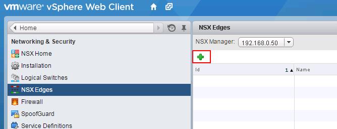
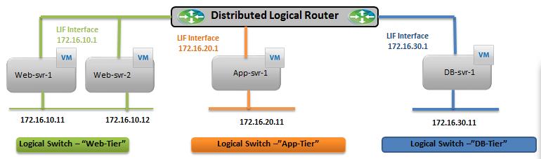
Below is my lab Topology. I am going to establish communication between 3 Logical switch “Web-Tier” ,”App-Tier” & “DB-Tier” using  Logical Router “LDR-001″VMware NSX-Logical Routing-Lap TopologyTo Deploy Logical Router -> Login to Web Client ->Networking & Security -> NSX Edges -> Click on + to add NSX Logical router.
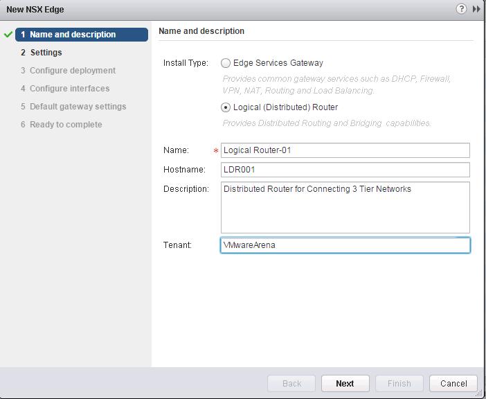
VMware NSX- Logical Routing-5Select the Logical (Distributed) Router from the radial menu and Provide in the Name, Hostname and Description for the Logical Router and Click Next.
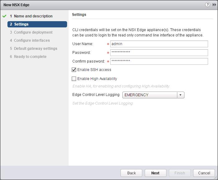
VMware NSX- Logical Routing-6Set an administrative password and username. Select the checkbox Enable SSH access and click on Next.
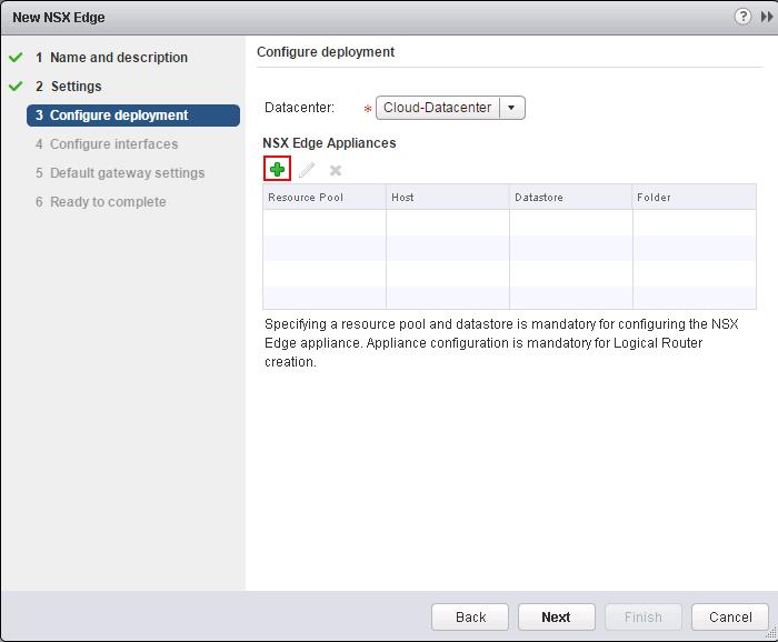
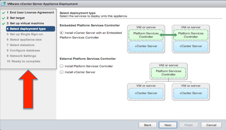
VMware NSX- Logical Routing-7Click on + under NSX Edge Appliances and we need to define where we want to deploy the DLR Control VM.
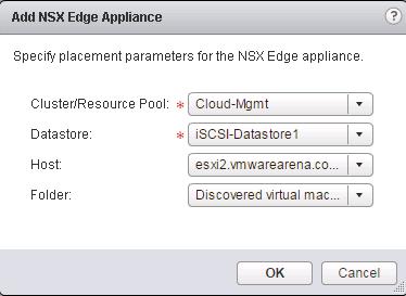
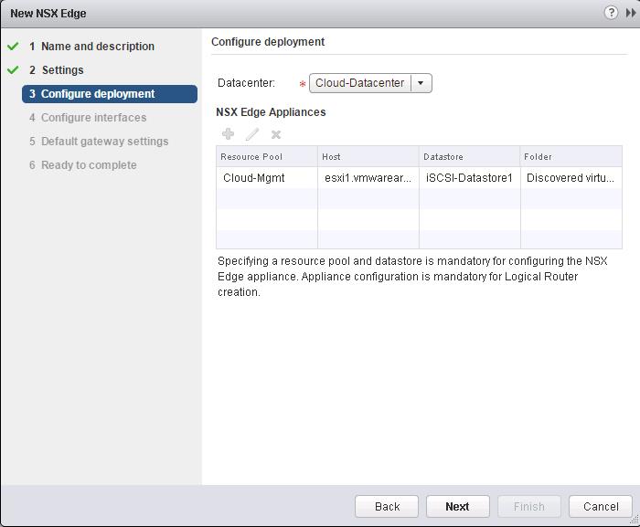
VMware NSX- Logical Routing-8Specify the Cluster, Datastore, Host and Folder to deploy the DLR Control VM and click on Ok to deploy the Control VM.

VMware NSX- Logical Routing-9

Click on NextVMware NSX- Logical Routing-9-1

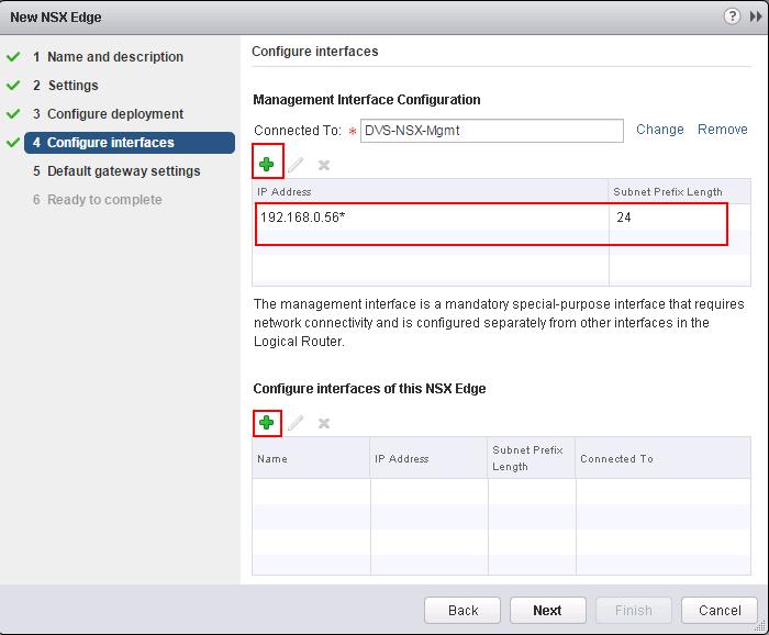
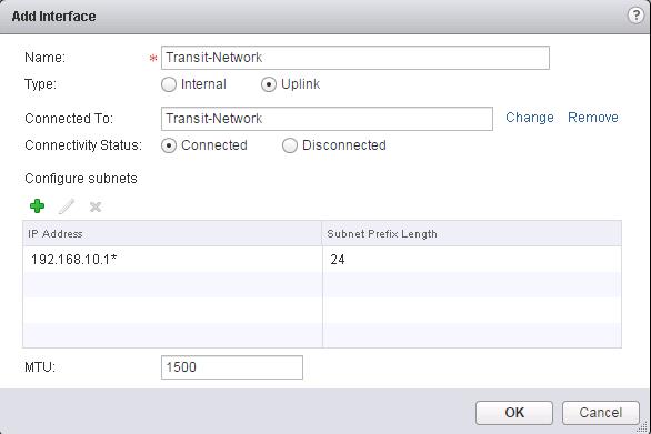
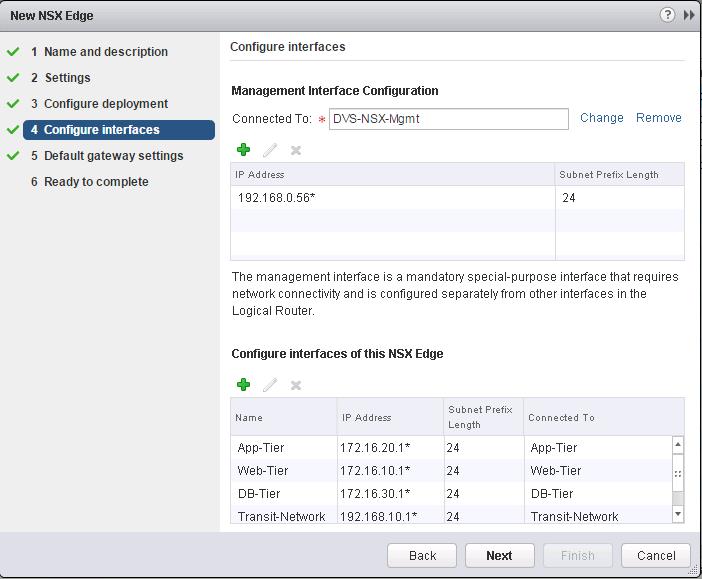
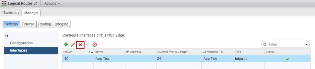
We need to specify the Management interfaces and Logical Interface (LIF).Management Interface is for access with SSH to Control VM. LIF interface needed to be configured in Second Table below “Configure Interfaces of this NSX Edge”. Click on Select Option under Management interface Configuration to select the PortGroup to connect to the Control VM Management Interface and assign the IP address for the Management interface of the Logical Router.Click on + symbol under Configure interfaces of this NSX Edge.VMware NSX- Logical Routing-10
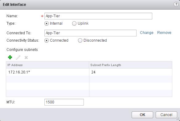
Create a interface called “Transit-Network” and Select the type as “Uplink”. Click on Connected To and select the  logical switch”Transit-Network” to connect to and Assign the Ip address for this LIF (Logical interface). I am going to use this Transit interface to establish the communication between Logical router to Physical network by connecting it to NSX edge device. Which we will discuss in upcoming posts.VMware NSX- Logical Routing-11
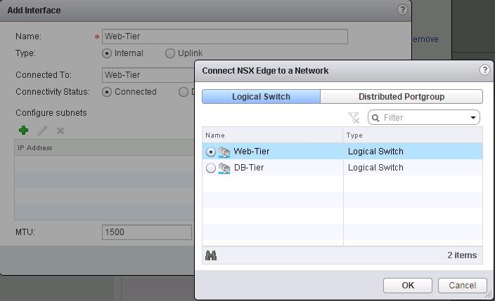
Enter the Name for this Logical interface(LIF)  as “App-Tier” and Select the type as “Internal” and Click on Connected To and select the Logical Switch “App-Tier” and Enter the IP address for this LIF (Logical Interface) as “172.16.20.1″.VMware NSX- Logical Routing-12
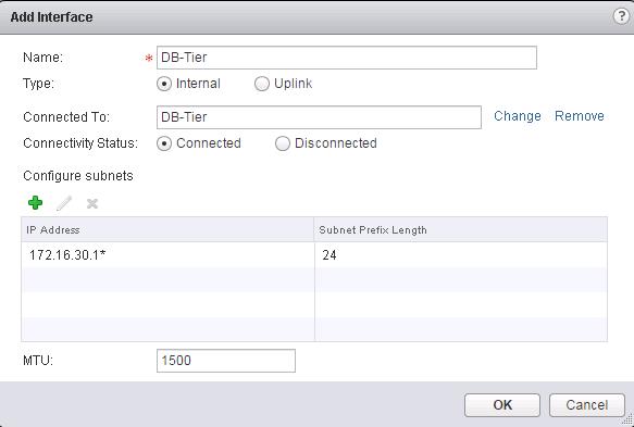
Create a interface called”Web-Tier” and click on Connected To and Select the logical switch “Web-Tier” and enter the IP address for this interface.VMware NSX- Logical Routing-13Create a Logical Interface “DB-Tier” and connect to the Logical Switch “DB-Tier” and assign the IP address for this LIF interface and click on Ok.
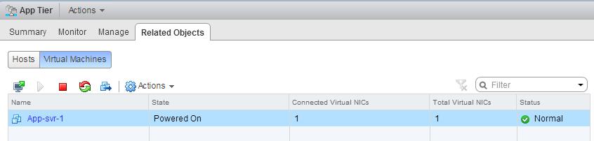
VMware NSX- Logical Routing-14
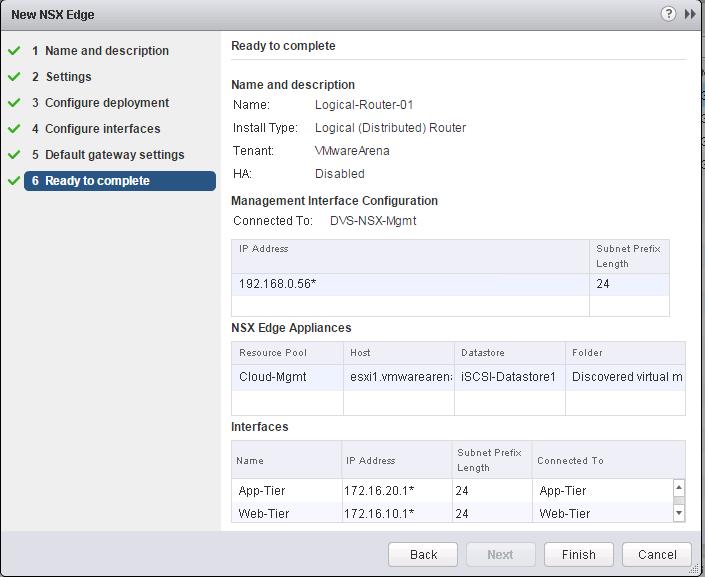
I have Connected 4 Logical Switches “Transit-Network”, “Web-Tier”, “App-Tier” and “DB-Tier” as the interfaces for this logical ineterface. In Simple terms, This Logical router provides routing between the VM’s connected to this Logical switches.VMware NSX- Logical Routing-15Review the Configured settings for the Distributed Logical Router and Click on Finish.
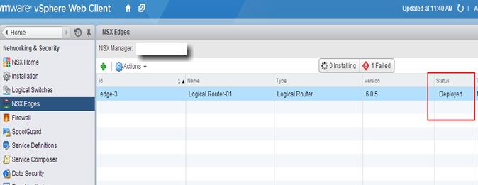
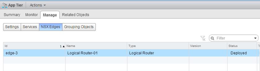
VMware NSX- Logical Routing-16Once Logical router is deployed, you can see the status of the DLR deployment under NSX Edges. Wait until Status of DLR  changed to “Deployed”.VMware NSX- Logical Routing-17


Ping Test To Prove the Distributed Routing:
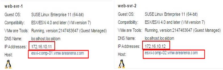
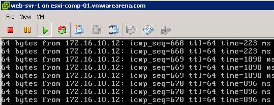
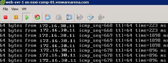
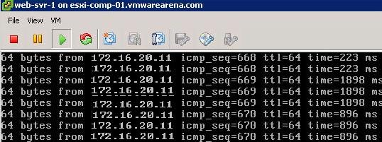
NSX-Logical RoutingPing Test between different Virtual Machines connected to different logical switches is able to reach each other. It proves that Logical Routing is working.

VMware NSX-Logical Switch Creation -8

VMware NSX- Logical Routing-18

VMware NSX- Logical Routing-19We are done with configuring Distributed routing. I hope this is informative for you. Thanks for Reading!!. Be Social and share it in Social media, if you feel worth sharing it.

VMware NSX – Backup & Restore VMware NSX Manager Data

$
0
0

When comes to infrastructure systems, It is always a question of what will be recovery option. It is very normal that system may get crashed due to some issues. It will be always a question in the mind that how would we recover the system and what will be the backup stratergy. In repsonse to the NSX Manger, We can backup and restore the NSX Manager data from NSX Manager management web page. You can back up and restore your NSX Manager data, which can include system configuration, events, and audit log tables. Configuration tables are included in every backup. Backups are saved to a remote location that must be accessible by the NSX Manager. In this post, We will discuss about how to configure and schedule the NSX Manager data. Let’s take a look at the detailed step by step procedure to configure the NSX Manager backup & restore.

Backup NSX Manager Data:

Login to NSX Manager management page using the below URL:

https:<NSX-Manager IP_or Name>

In Home Page of NSX Manager,click Backups & Restore Under Appliance Management

NSX Manager-Backup & Restore_1

Click on Change to specify the FTP Server Settings to store the NSX Manager Backup files.

NSX Manager-Backup & Restore_2Enter the Below information to specify the NSX Manager Backup settings:

  • Enter the IP address or host name of the FTP server, which is going to store the backup files.
  • From the Transfer Protocol drop-down menu, select either SFTP or FTP, based on what the destination supports and Edit the default port if required.
  • Enter the user name and password which is required to login to the Backup System i.e FTP server
  • In the Backup Directory field, type the absolute path of the FTP Folder, where backups will be stored.
  • Type a text string in Filename Prefix. This text is prepended to each backup filename for easy recognition on the backup system. For example, if you type NSXBCKP, the resulting backup file will be  named as NSXBCKPHH_MM_SS_DayDDMonYYYY.
  • Type the pass phrase to secure the backup and Click OK.

NSX Manager-Backup & Restore_3

Click on Change next to Scheduling to schedule the backup of  NSX Manager Data.

NSX Manager-Backup & Restore_4Specify the below details to Schedule the NSX Manager Data:

  • From the Backup Frequency drop-down menu, select Hourly, Daily, or Weekly based on your requirement. The Day of Week, Hour of Day, and Minute drop-down menus are disabled based on the selected frequency. For example, if you select Daily, the Day of Week drop-down menu is disabled as this field is not applicable to a daily frequency.
  • I prefer to do Weekly backup.For a weekly backup, select the day of the week and hour and Minute that the data should be backed up.
  • Click Schedule to save the NSX Manager backup schedule.

NSX Manager-Backup & Restore_5

Click on Change settings for Exclude Option to exclude any of the data during NSX Manager Backup.

NSX Manager-Backup & Restore_6For Demo Purpose, I have excluded the Flow Records from the NSX Manager backup. and click on OK.

NSX Manager-Backup & Restore_7

All Backup Settings are configured. Click on Backup to initiate the immediate backup of NSX Manager.

NSX Manager-Backup & Restore_8Click on Start to start the backup.

NSX Manager-Backup & Restore_9

Once Backup is completed, You will be able to see the Last backup information like Filename, date and Size of the backup file.

NSX Manager-Backup & Restore_10


I can see the same information ,when i browse towards the FTP server backup directory.

NSX Manager-Backup & Restore_11


Restore NSX Manager Data:

To Restore the NSX Manager Data, Select one of the Backup file and click on Restore option to restore the NSX Manager Data.

NSX Manager-Backup & Restore_12Restoring NSX Manager data will require restart of server and Appliance management will be unavailable for sometime. Click on Yes. That it.  NSX Manager Data will be restored.

NSX Manager-Backup & Restore_13That’s it.I hope this is informative for you. Thanks for Reading!!!. Be Social and Share it in social media, if you feel worth sharing it.

VMware NSX – Unable to Delete/Remove NSX Logical Switch

$
0
0

I recently worked with my NSX Setup and I tried to remove/Delete one of the Logical Switch in my Lab.  I am getting the error Message “Resources are still in Use”.  We come to know from the error message that some of the resources like VM’s  are utilizing this Logical switch. That’s why we are not able to delete this Logical Switch. Yes, It is correct. Let’s discuss in this, How to verify what are all the resources are actively utilizing the NSX Logical Switch.

Delete Logical Switch_2

Login to vSphere Web Client -> Network & Security ->Logical Switch -> Select the Logical Switch which you are attempting to delete.

Delete Logical Switch_1

Double Click the Logical Switch, Which you attempt to delete. Select the Related Objects tab, then click on the Virtual Machines Tab.

If you have any remaining virtual machines connected to the Logical Switch you are attempting to delete, migrate them to another Logical Switch. In our Case, I see the VM named “App-svr-1″.which is still connected to the logical switch “App Tier”. So Migrate this VM to Different port Group by Edit settings.

Delete Logical Switch_3Ok. We have migrated the VM to different Port Group. I tried to delete the Logical Switch. I was Getting the error message ”Resources are still in Use”. Yes. There is one more resource which we need to verify . Which Is whether this Logical Switch is connected to any of the NSX Edge Device or DLR (Distributed Logical Router).

Double click the Logical Router which you are attempting to delete. Click on the Manage tab, then click on the NSX Edges button.

If you have any connections (interfaces) to an NSX Edge you will need to remove them I can see this Logical Switch “App Tier” have active connections(interfaces) to the Logical Router. We need to remove them.

Delete Logical Switch_4To delete the NSX Logical Router Interface, Click on vSphere Web Client -> Network & Security -> NSX Edges ->Select and Double click the Edge Device, where you have active connections to Logical Switch. -> Click Manage Tab -> Settings -> Interfaces -> Select the Interface which connected to your Logical Switch -> Click on X Symbol to delete the interface.

Delete Logical Switch_5


Once both VM’s and Interface(LIF) which is attached to Edge Devices are removed, our Logical Switch don’t have any resources attached to it. Let’s Delete the Logical Switch by Click on X symbol to delete the Logical Switch.

Delete Logical Switch_6Once Logical Switch is deleted ,you can see task “Delete Distributed Port Group” completed in Recent Tasks tab. Which removes the Port Group which relates to the Logical Switch.

Delete Logical Switch_7That’s it. We are done with deleting the NSX Logical Switch. I hope this is informative for you. Thanks for Reading !!!. Be Social and share it in social media, if you feel worth sharing it.

VMware NSX – How to Manually Install NSX VIBS on ESXi Host

$
0
0

Job of vSphere Administrators is not so limited to GUI. You should be always available with troubleshoot your issues from command line or CLI.This also applies, when you are dealing with VMware NSX. We have already discussed about Preparing your vSphere CLuster and Host by installing NSX VIBS from Network & Security plugin from vSphere Web Client. It always a situation that the installation of NSX VIB’s may fail due to some reason and we as vSphere admin should have to troubleshoot and fix the installation issues. I have faced one of the issue when i prepare my cluster/ ESXi host for NSX. Let’s take a detailed look at setp by step procedure to manually install NSX VIBs on the ESXi host.

Download NSX VIBs from the below URL:

https://<NSx-Mgr-IP>/bin/vdn/vibs/5.5/vxlan.zip

If you extract the downloaded “vxlan.zip”. Below are contents of the vxlan.zip.  It Contains the 3 VIB files

  1. esx-vxlan
  2. esx-vsip
  3. esx-dvfilter-switch-security

One VIB enables the layer 2 VXLAN functionality, another VIB enables the distributed router, and the final VIB enables the distributed firewall.

Install NSX VIBs on ESXi Host_1

Extract the vxlan.zip file and Copy the folder into the Shared Datastore or on the local folder of the ESXi host using WinScp. I have copied the folder into my ESXi host in /tmp directory. Let’s install the NSX VIBs one by one in the ESXi host.

Install NSX VIBs on ESXi Host_2

Install the “esx-vxlan” vib on the ESxi host using the below command:

 esxcli software vib install –no-sig-check -v /tmp/vxlan/vib20/esx-vxlan/VMware_bootbank_esx-vxlan_5.5.0-0.0.2107100.vib

Install NSX VIBs on ESXi Host_3

Install the “esx-vsip” vib on the ESXi host using the below command:

esxcli software vib install –no-sig-check -v /tmp/vxlan/vib20/esx-vsip/VMware_bootbank_esx-vsip_5.5.0-0.0.2107100.vib

Install NSX VIBs on ESXi Host_4

Install the “esx-dvfilter-switch-security” vib on the ESXi host using the below command:

esxcli software vib install –no-sig-check -v /tmp/vxlan/vib20/esx-dvfilter-switch-security/VMware_bootbank_esx-dvfilter-switch-security_5.5.0-0.0.2107100.vib

Install NSX VIBs on ESXi Host_5

That’s it. We are done with manually installing NSX VIBs on ESXi host. This operations don’t require reboot of the ESXi host. Even this can be done when active workloads are running on the ESXi host. I hope this is informative for you. Thanks for reading. Be Social and share it in social media, if you feel worth sharing it.


Impact of Changing Memory Reservation settings on Powered-on Virtual Machine

$
0
0

As a VMware Admin, We would have received lot of support request. Most of them are related to the resource settings of Virtual Machine either increasing or decreasing the VM resources and other common request will be configuring VM reservation especially VM memory reservation settings. When it comes to VM memory reservation settings, We recommend the support team to Power off the VM to configure the VM memory reservation settings for the changes to take effect. We need to ask the question what will happen ,if i configure VM memory reservation setting is configured on powered on virtual machine. This article talks about the impact of changing VM memory reservation settings on the fly.

I have a virtual machine called “DB-Tier” configured with 4 GB of memory  without any  memory reservation configured.

Impact of VM Memory reservation on Power on VM_1


Every powered on Virtual Machine on the ESxi host will have a.vswp file (swap file ) associated with it. This .vswp file will stored in the Virtual Machine directory by default. This .vswp file will be automatically deleted, when virtual machine is powered off. By default, .vSwp file size is same as the configured memory size of the Virtual machine. This .vswp file will be used, if the host is actively over-committed and higly utilized. In that instance, ESXi host will start swapping the VM memory from the host’s physical memory into .vswp file just like as operating system does when running out of memory. ESXi host have many memory management techniques like TPS (Transparent page sharing), Ballooning and Memory Compression. Swapping will be last restore memory management technique handled by ESXi host.

VM configured with 4 Gb of memory has 4 Gb .vswp file  created in the virtual machine directory.

Impact of VM Memory reservation on Power on VM_2

Configuring Memory reservation of Powered-on Virtual Machine :

Memory reservation is a guarantee of memory resources for a virtual machine from the available physical resources. If you reserve 2 Gb of memory on a guest with 4 Gb of RAM, you are guaranteeing that the guest will always have access to 2 Gb of physical memory on the host.

Setting a 2 Gb reservation on a guest configured with 4 Gb of RAM means you will never swap more than 2 GB out to the .vswp file. Powering on this VM will result in a .vswp file of 2 GB file.

I have configured the Memory reservation of this powered on Virtual machine to 2 GB.  As per the above discussion, if 2 Gb out of 4 Gb of memeory is reserved, .vswp file should also change it to 2 Gb. Since i have configured reservation on powered-on vm, .vswp file was not reduced form 4 gb to 2 Gb.

Impact of VM Memory reservation on Power on VM_3

once I powered off the VM and Powered on again ,.vswp file automatically reduced from 4GB to 2 GB.

Impact of VM Memory reservation on Power on VM_4

Removing the VM Memory Reservation of Powere-on Virtual Machine:

For the VM  configured with 2 Gb of reservation out of 4 GB, .vswp file size will 2 Gb.  When i changed the VM reservation from 2 Gb to 0 MB, my .vswp file automatically increased to 4 GB of size.

Impact of VM Memory reservation on Power on VM_5

Final Observation:

  • Swap(.vswp) file will be created during VM power on and deleted at power off
  • Swap (.vswp) file size = Allocated memory minus Reserved Memory (VM Configured Memory – VM reserved memory)
  • Swap file size will increase on the fly, when you reduce the Memory Reservation.
  • Swap file size will not decrease as reservation is increased (new size will take effect at next VM power cycle)

I hope this post will helps you to understand the impact of changing the VM memory reservation settings on Powered on Virtual machine. Thanks for Reading!!!. Be Social and share it in social media, if you feel worth sharing it.

VMware NSX – How to Manually Remove NSX VIBs from ESXi Host?

$
0
0

As we already discussed many times, Job of vSphere Administrators is not so limited to GUI. You should be always available with troubleshoot your issues from command line or CLI.This also applies ,when you are dealing with VMware NSX. We have already discussed about manually installing NSX VIBS from CLI of ESXi host. There are some situation that the installation or Uninstallation of NSX VIB’s may fail due to some reason and we as vSphere admin should have to troubleshoot and fix the installation/Uninstallation issues. I have faced one of the issue, when i try to uninstall the NSX components from vSphere Web Client. Let’s take a detailed look at step by step procedure to manually remove NSX VIBs on the ESXi host.

You can UnPrepare the Host/Cluster from vSphere Web Client -> Network & Security -> Installation ->Host Preparation -> Click on UnInstall to unprepare/ Uninstall the NSX VIBs from ESXi host.

Manually Remove NSX VIBS from ESXi_2Sometimes, The Uninstall step may get failed due to some communication issues. We should also be ready to manually remove the NSX VIBs installed on the ESXi host from Command Line. There are 3 VIBs related to NSX which we need to remove from the ESXi host.

  1. esx-vxlan
  2. esx-vsip
  3. esx-dvfilter-switch-security

One VIB enables the layer 2 VXLAN functionality, another VIB enables the distributed router, and the final VIB enables the distributed firewall.

Manually Remove NSX VIBs from ESXi Host:

Move your running Virtual Machines to differet host in the Cluster using vMotion. Place your ESXi Host into Maintenance Mode.

To remove the “esx-vxlan” VIB , execute the below command:

esxcli software vi remove -n esx-vxlan

To remove the “esx-vsip” VIB , execute the below command:

esxcli software vi remove -n esx-vxlan

To remove the “esx-dvfilter-switch-security” VIB , execute the below command:

esxcli software vi remove -n  esx-dvfilter-switch-security

Manually Remove NSX VIBS from ESXi_1Once you have removed all the 3 NSX VIBs, Reboot the ESXi host for the Changes to take effect. I hope this is informative for you. Thanks for Reading !!!. Be Social and share it in social media, if you feel worth sharing it.

How vCenter Assigns MAC Addresses to VMware Virtual Machines?

$
0
0

I have been asked by many VMware Administrators about how MAC addresses are assigned to Virtual Machine?. We all aware that first 3 octet will be 00:50:56. The first three parts never change. This is the VMware Organizational Unique Identifier (OUI). How does other 3 octets are generated may be biggest question in our mind. Let’s discuss about How MAC addresses are assigned to VMware Virtual Machines by vCenter server. This post only applicable to the VM MAC generation, in which ESXi host is managed by vCenter Server. ESXi host which is not managed by vCenter server will have different mechanism to generate the MAC address for Virtual Machine.

As we aware that, First 3 Octects will be 00:50:56. This is the VMware Organizational Unique Identifier (OUI). How does 4th  octet of VM MAC address are calculated. Let’s begin the Calculation.

4th Octet of MAC = (128+ vCenter Instance ID) Convert it to Hexadecimal

To get the vCenter Server Instance ID -> Login to vSphere Client ->Administration -> vCenter Server Settings -> Runtime Settings. Note down the vCenter Server Unique ID. My vCenter Server Unique ID is 24.

VMware VM MAC Assignment_1

VMware VM MAC Assignment_2

How 4th Octet of the VM MAC Address is Calculated?

The automatically generated MAC address has a fourth octet is equal to 128 + the vCenter instance ID converted to hexadecimal.

4th Octet of MAC = (128+ vCenter Instance ID) Convert it to Hexadecimal

= 128+24 = 152

VMware VM MAC Assignment_4

4th Octet of VM MAC = 98 (Conversion of 152 to Hexadecimal)

I have confirmed the Same from the few of Virtual Machine MAC Address. 4 octet is assigned as “98″.

VMware VM MAC Assignment_5The last two bytes are assigned in mechanism, so that each MAC address is assigned would be unique. I hope this is informative for you. Thanks for Reading!!!. Be Social and share it in social media, if you feel worth sharing it.

vSphere 6.0 New Features – Content Library

$
0
0

Content Library is the new feature introduced with vSphere 6.0. vCenter’s Content Library provides simple and effective management of VM templates, vApps, ISO images and scripts for vSphere admins. Content Library centrally stores VM templates, vAPPs, ISO images and scripts. This content can be synchronized across sites and vCenter servers in your organization. In many environment,  NFS mount has been used to store all ISO images and templates but Content Library will simply the management of storing VM templates , vApps and ISO images either backed up by NFS mount or Datastores. Contents of Content library are synchronized with other vCenter Servers and ensure that workloads are consistence across your environment.

vSphere 6.0 -Content Library_1Graphic Thanks to VMware.com

Benefits of vCenter Content Library:

  • Content Library provides storage and versioning of files including VM templates, ISOs and OVFs.
  • You can publish the Content Library  to public or Subscribe content library to get it synchronized with other vCenter Content Library. You will be able to Publish or Subscribe between vCenter -> vCenter & vCD -> vCenter

vSphere 6.0 -Content Library_2

  • Content Library basically backed up by vSphere Datastores or NFS file system,which uses this storage to store the library items like VM Templates, ISOs and OVFs.

vSphere 6.0 -Content Library_3

  • You can perform the deployment from the contents stored (templates, ISOs and appliances) in content library to host and clusters. and you can also perform deployment into Virtual Data center.

Let’s plan to utilize the vCenter Content Library to perform centralized management of VM templates, ISOs and OVFs by upgrading our infrastructure to vSphere 6.0. I hope this is informative for you. Thanks for reading!!!. Be social and share it in social media, if you feel worth sharing it.

vSphere 6.0 Related Articles:

vSphere 6.0 vMotion Enhancements – vMotion Across vSwitches and vCenter Servers

$
0
0

vSphere 6.0 not only comes with great scalability but also with a  various new features, which unlocks your existing limitations with the vMotion. With the earlier versions of vSphere, vMotion requires an exact similar network configuration between the ESXi hosts and also at the vSwitch level. In previous versions of vSphere, we were not allowed to perform the vMotion between the vSphere distributed Switches. It was only limited within the dvswitch. with vSphere 6.0, vMotion is allowed across vSwitches and even vCenter Servers. Let’s take a detailed look  at vSphere 6.0 vMotion enhancements.

vMotion Across Virtual Switches

vMotion is no longer restricted by the network configured with vSwitch. with vSphere 6.0, It is possible to perform vMotion across Virtual switches (Standard switch or Distributed Switch),Which transfers all the VDS port metadata during the vMotion. It is entirely transparent to the Guest VM’s and No downtime is required to perform this vMotion operation across vSwitches. Only one requirement for the vMotion across vSwitches is that you should have L2 VM Connectivity.

vSphere 6.0 -vMotion Enhancements_1Graphic Thanks to VMware.com

With vSphere 6.0, It is possible to perform vMotion of VM’s in 3 different ways:

  • vMotion of VMs from Standard switch to Standard switch (VSS to VSS)
  • vMotion of VMs from Standard switch to Distributed Switch (VSS to VDS)
  • vMotion of VMs from Distributed Switch to Distributed switch (VDS to VDS)

vMotion Across vCenter Servers

With vSphere 6.0, vMotion across vCenter server allows you to simultaneously change the Compute, Storage, Networks and management. It leverage the vMotion with unshared Storage. In simple terms, VM1 is running on certain Host/Cluster running on certain Datastore and managed by vCenter 1 can be vMotioned to different ESXi host having different datastores managed by another vCenter server called vCenter 2.

vSphere 6.0 -vMotion Enhancements_2Graphic Thanks to VMware.com

Requirement for vMotion Across vCenter Servers:

  • Support for vMotion across vCenter server supports from vSphere 6.0 and later versions
  • Destination vCenter server instance should have same SSO domain as source vCenter and this operation is possible via UI. Using API, it is possible with different SSO domain.
  • 250 Mbps network bandwidth per vMotion operation

Properties of vMotion Across vCenter Servers:

  • Same VM UUID is maintained across vCenter Server instances
  • All the VM related historical data like Events, Alarms and Tasks are preserved after the vMotion operation
  • HA properties are Preserved and DRS anti-affinity rules are honored during the vMotion operation

Long Distance vMotion

With vSphere 6.0, vMotion for Long-Distance supports upto 100+ms RTTs(which was only 10 ms in previous versions). Long-Distance vMotion allows you to vMotion your VMs from one datacenter to other datacenter of your organization. Below are few of the use cases of the Long Distance vMotion:

  • SRM/DA testing
  • Permanent migrations
  • Disaster avoidance
  • Multi-site load balancing
  • Migration between Datacenters or Cloud Platform

Network Requirements of Long Distance vMotion:

  • All the vCenters servers must connect via Layer 3 Network.
  • VM network should have L2 connectivity and same VM IP address available at destination location
  • vMotion network should have L3 connectivity and 250 MBps per vMotion Operation
  • For NFC network,routed L3 through Management Network or L2 connection
  • For Networking, L4-L7 services manually configured at destination

I hope this is informative for you. Thanks for Reading!!!. Be social and share it in social media, if you feel worth sharing it.

vSphere 6.0 Related Articles:

vSphere 6.0 – What’s New in VMware Fault Tolerance (FT)

$
0
0

VMware Fault Tolerance (FT) is being one of my favorite feature but because of its vCPU limitation, It was not helping to protect the Mission Critical applications. With vSphere 6.0, VMware broken the limitation lock of Fault Tolerance. FT VM now Supports upto 4 vCPUs and 64 GB of RAM (Which was 1 vCPu and 64 GB RAM in vSphere 5.5). With this vSMP support, Now FT can be used to protect your Mission Critical applications. Along with the vSMP FT support, There are lot more features has been added in FT with vSphere 6.0, Let’s take a look at what’s new in vSphere 6.0 Fault Tolerance(FT).

vSphere 6.0 - FT_1Graphic thanks to VMware.com

Benefits of Fault Tolerance

  • Continuous Availablity with Zero downtime and Zero data loss
  • NO TCP connections loss during failover
  • Fault Tolerance is completely transparent to Guest OS.
  • FT doesn’t depend on Guest OS and application
  • Instantaneous Failover from Primary VM to Secondary VM in case of ESXi host failure

What’s New in vSphere 6.0 Fault Tolerance

  • FT support upto 4 vCPUs and 64 GB RAM
  • Fast Check-Pointing, a new Scalable technology is introduced to keep primary and secondary in Sync by replacing “Record-Replay”
  • vSphere 6.0, Supports vMotion of both Primary and Secondary Virtual Machine
  • With vSphere 6.0, You will be able to backup your virtual machines. FT supports for vStorage APIs for Data Protection (VADP) and it also supports all leading VADP solutions in Market like symantec, EMC, HP ,etc.
  • With vSphere 6.0, FT Supports all Virtual Disk Type like EZT, Thick or Thin Provisioned disks. It supports only Eager Zeroed Thick with vSphere 5.5 and earlier versions
  • Snapshot of FT configured Virtual Machines are supported with vSphere 6.0
  • New version of FT keeps the Separate copies of VM files like .VMX, .VMDk files to protect primary VM from both Host and Storage failures. You are allowed to keep both Primary and Secondary VM files on different datastore.

vSphere 6.0 - FT_2 Graphic thanks to VMware.com

Difference between vSphere 5.5 and vSphere 6.0 Fault Tolerance (FT)

Difefrence between FT 5.5 amd 6.0

I hope we all are ready to build and protect your Mission Critical VM’s with Fault Tolerance. Thanks for Reading!!! Be Social and share it in social media, if you feel worth sharing it.

vSphere 6.0 Related Articles:

vSphere 6.0 New Features – What is VMware Virtual Volumes (VVols)?

$
0
0

Virtual Volumes (VVols) is one the new feature addition with vSphere 6.0. Virtual volumes are encapsulations of virtual machine files, virtual disks, and their derivatives. Virtual volumes are stored natively inside a storage system that is connected through Ethernet or SAN. They are exported as objects by a compliant storage system and are managed entirely by hardware on the storage side. Typically, a unique GUID identifies a virtual volume.

Virtual volumes are not preprovisioned, but created automatically when you perform virtual machine management operations. These operations include a VM creation, cloning, and snapshotting. ESXi and vCenter Server associate one or more virtual volumes to a virtual machine.

vSphere 6.0 -Virtual Volumes_1

Currently all storage is LUN-centric or volume-centric, especially when it comes to snapshots, clones and replication. VVols makes it storage VM-centric. With VVols, most of the data operations can be offloaded to the storage arrays. VVols goes much further and makes storage arrays aware of individual VMDK files.Virtual volumes encapsulate virtual disks and other virtual machine files as natively stored the files on the storage system.

How Many Virtual Volumes (VVols) created Per Virtual Machine ?

For every VM a single VVol is created to replace the VM directory in today’s system.

  • 1 config VVol  represents a small directory that contains metadata files for a virtual machine. The files include a .vmx file, descriptor files for virtual disks, log files, and so forth.
  • 1 VVol for every virtual disk (.VMDK)
  • 1 VVol for swap, if needed
  • 1 VVol per disk snapshot and 1 per memory snapshot

Additional virtual volumes can be created for other virtual machine components and virtual disk derivatives, such as clones, snapshots, and replicas.

Major Components of VMware Virtual Volumes (VVols):

There are 3 important objects in particular related to Virtual Volumes(VVols) are the storage provider, the protocol endpoint and the storage container. Let’s discuss about each of the 3 items:

Storage Providers:

  • A VVols storage provider, also called a VASA provider. Storage provider is implemented through VMware APIs for Storage Awareness (VASA) and is used to manage all aspects of VVols storage.
  • Storage provider delivers information from the underlying storage,so that storage container capabilities can appear in vCenter Server and the vSphere Web Client.
  • Vendors are responsible for supplying storage providers that can integrate with vSphere and provide support to VVols.

vSphere 6.0 -Virtual Volumes_2

Storage Container:

  • VVols uses a storage container, which is a pool of raw storage capacity or an aggregation of storage capabilities that a storage system can provide to virtual volumes.
  • The storage container logically groups virtual volumes based on management and administrative needs. For example, the storage container can contain all virtual volumes created for a tenant in a multitenant deployment, or a department in an enterprise deployment. Each storage container serves as a virtual volume store and virtual volumes are allocated out of the storage container capacity.
  • Storage administrator on the storage side defines storage containers. The number of storage containers and their capacity depend on a vendor-specific implementation, but at least one container for each storage system is required.

Protocol EndPoint (PE):

  • Although storage systems manage all aspects of virtual volumes, ESXi hosts have no direct access to virtual volumes on the storage side. Instead, ESXi hosts use a logical I/O proxy, called the protocol endpoint, to communicate with virtual volumes and virtual disk files that virtual volumes encapsulate.
  • ESXi uses protocol endpoints to establish a data path on demand from virtual machines to their respective virtual volumes.
  • Each virtual volume is bound to a specific protocol endpoint. When a virtual machine on the host performs an I/O operation, the protocol endpoint directs the I/O to the appropriate virtual volume. Typically, a storage system requires a very small number of protocol endpoints. A single protocol endpoint can connect to hundreds or thousands of virtual volumes.

VVols Datastore:

  • A VVols datastore represents a storage container in vCenter Server and the vSphere Web Client.
  • After vCenter Server discovers storage containers exported by storage systems, you must mount them to be able to use them. You use the datastore creation wizard in the vSphere Web Client to map a storage container to a VVols datastore.

vSphere 6.0 -Virtual Volumes_VVols Datastore

  • The VVols datastore that you create corresponds directly to the specific storage container and becomes the container’s representation in vCenter Server and the vSphere Web Client.
  • From a vSphere administrator prospective, the VVols datastore is similar to any other datastore and is used to hold virtual machines. Like other datastores, the VVols datastore can be browsed and lists configuration virtual volumes by virtual machine name. Like traditional datastores, the VVols datastore supports unmounting and mounting. However, such operations as upgrade and resize are not applicable to theVVols datastore. The VVols datastore capacity is configurable by the storage administrator outside of vSphere.

I hope this helps you to understand the basics about VMware Virtual Volumes (VVOls) available with vSphere 6.0. Thanks for Reading!!!. Be Social and share it in social media,if you feel worth sharing it.

vSphere 6.0 Related Articles:


vSphere 6.0 – What’s New in vCenter Server Appliance(vCSA) 6.0

$
0
0

vCenter Server Appliance (vCSA) is a Security hardened base Suse (SLES 11 SP3) operating system packaged with vCenter server and vFabric Postgres database.  vCSA appliance supports Oracle as external database. vCenter Server Appliance contains all of the necessary services for running vCenter Server 6.0 along with its components. As an alternative to installing vCenter Server on a Windows host machine, you can deploy the vCenter Server Appliance. It helps you quickly deploy vCenter Server without spending time to prepare windows operating system for vCenter server Installation. vCSA now supports most of the features which is supported with windows version of vCenter server.

What’s New with vCenter Server Appliance (vCSA) Installation:

As compared with the deployment of previous version of vCSA, vCSA 6.0 is different. Prior to vSphere 6.0, vCSA can be deployed using OVF template but It  should be deployed using ISO image in vCSA 6.0. You need to download .iso installer for the vCenter Server Appliance and Client Integration Plug-in.

vCSA 6.0 - Guided Installer

Install the Client Integration plugin and double-click html” file in the software installer directory,which will allow access to the VMware Client Integration Plug-In and click Install or Upgrade to start the vCenter Server Appliance deployment wizard. You will be provided with various options during the deployment including the Deployment type of vCenter Server.

vCenter 6.0 Deployment Methods:

Embedded Platform Services Controller:

All services bundled with the Platform Services Controller are deployed on the same virtual machine as vCenter Server. vCenter Server with an embedded Platform Services Controller is suitable for smaller environments with eight or less product instances.

External Platform Services Controller:

The services bundled with the Platform Services Controller and vCenter Server are deployed on different virtual machines.You must deploy the VMware Platform Services Controller first on one virtual appliance and then deploy vCenter Server on another appliance. The Platform Services Controller can be shared across many products. This configuration is suitable for larger environments with nine or more product instances.

vCSA 6.0 - Deployment Types

 vCSA 6.0 Appliance Access:

As Compared with the Previous Versions of vCSA, vCSA 6.0 appliance access has been modified a bit. vCSA no more having admin URL with port 5480 to control and configure the vCenter Server appliance. Now there are 3 Methods to access the vCSA appliance

  • vSphere Web Client UI
  • Appliance Shell
  • Direct Control User Interface (DCUI)

With DCUI added with vCSA. Look and Feel of vCSA is very similar to ESXi host. Black box model.

vCSA 6.0 Appliance Sizing:

During vCSA 6.0 deployment, you will be asked to select the deployment size of vCSA appliance. There are 4 default out-of-box sizes available with vCSA deployment.

vCSA 6.0 - Appliance Sizes

vCSA 6.0 - Appliance Size

Comparison  between vCenter  6.0 Windows and vCSA 6.0

vCSA now supports most of the features which is supported with the windows version of vCenter server.  I would like to provide quick comparison table between vCenter windows version and vCenter server appliance with embedded database.

vSphere 6.0 - feature Comparision betwwen vCenter windows and vCSA

I hope this post helps you to understand the new features and changes about vCenter Server appliance 6.0. Thanks for reading!!!. Be social and share it in social media, if you feel worth sharing it.

vSphere 6.0 Related Articles:

vSphere 6.0 – New Configuration Maximums

$
0
0

VMware vSphere 6.0 introduced with lot of new enhancements and feature addition as compared with the previous versions of vSphere. In everyone’s mind, configuration maximum will be the first question during all vSphere releases. How big the platform supports?  I would like give a Quick walk through about New configuration maximums of vSphere 6.0. Which Supports a Monster VM and your VM will be ready for Mission Critical Applications. Let’s take a detailed look at New Configuration Maximum’s  available with VMware vSphere 6.0.

vsphere 6.0_vmwarearenaNew Configuration Maximums of vSphere 6.0:

  • vSphere 6.0 Clusters now supports 64 Nodes and 6,000 VM’s (Which was 32 Nodes and 4,000 VM’s in vSphere 5.5)
  • vCenter Server Appliance (vCSA 6.0) supports upto 1000 Hosts and 10,000 Virtual Machines with embedded vPostgres database
  • ESXi 6.0 host now supports support up to 480 physical CPUs  and 12 TB RAM (which was 320 CPUs and 4 TB in vSphere 5.5)
  • ESXi 6.0 host Supports 1000 VMs and 32 Serial Ports. (which was 512 VM per host in vSphere 5.5)
  • vSphere 6.0 VM’s will support  up to 128 vCPUs and 4TB vRAM (which was 64 vCPU’s and 1 TB of memory in vSphere 5.5)
  • vSphere 6.0 continuous to support 64 Tb Datastores as same as in vSphere 5.5
  • Increased support for virtual graphics including Nvidia vGPU
  • Support for New Operating systems like FreeBSD 10.0 and Asianux 4 SP3 
  • Fault Tolerance (FT) in vSphere 6.0 now supports upto 4 vCPUs (which was only 1 vCPU in vSphere 5.5)

I would like to provide a Quick Comparison table between the Configuration maximums of  vSphere 5.5 and vSphere 6.0:

vSphere 6.0 _Configuration Maxmimum

I hope we all are impressed with the Configuration maximums of vSphere 6.0. Let’s prepare our environment to build Monster and Mission critical VM’s with vSphere 6.0. I hope this is informative for you. Thanks for Reading !!!

vSphere 6.0 Related Articles:

vSphere 6.0 – What’s New in vCenter Server 6.0

$
0
0

In vSphere 6.0, you will notice considerably new terms, when installation vCenter Server 6.0. As similar to the previous versions of vCenter Deployment, You can install vCenter Server on a host machine running Microsoft Windows Server 2008 SP2 or later or you can deploy vCenter Server Appliance (VCSA). With vSphere 6.0, There are 2 different new vCenter Deployment Models.

  • vCenter with an embedded Platform Services Controller
  • vCenter with an external Platform Services Controller

One of the Considerable Change, you will notice with vCenter Server installation is deployment models and embedded database. Embedded database has been changed from SQL express edition to vFabric Postgres database. vFabric Postgres database embedded with vCenter installer is suitable for the environments with up to 5 hosts and 50 virtual machines and vCenter 6.0 continuous to support Microsoft and Oracle Database as external database. Let’s review the System requirements to install vCenter 6.0:

Supported Windows Operation System for vCenter 6.0 Installation:

  • Microsoft Windows Server 2008 SP2 64-bit
  • Microsoft Windows Server 2008 R2 64-bit
  • Microsoft Windows Server 2008 R2 SP1 64-bit
  • Microsoft Windows Server 2012 64-bit
  • Microsoft Windows Server 2012 R2 64-bit

 Supported Databases for vCenter 6.0 Installation:

  • Microsoft SQL Server 2008 R2 SP1
  • Microsoft SQL Server 2008 R2 SP2
  • Microsoft SQL Server 2012
  • Microsoft SQL Server 2012 SP1
  • Microsoft SQL Server 2014
  • Oracle 11g R2 11.2.0.4
  • Oracle 12c

Components of vCenter Server 6.0:

There are two Major Components of vCenter 6.0:

  • vCenter Server: vCenter Server product, that contains all of the products such as vCenter Server, vSphere Web Client,Inventory Service, vSphere Auto Deploy, vSphere ESXi Dump Collector, and vSphere Syslog Collector
  • VMware Platform Services Controller: Platform Services Controller contains all of the services necessary for running the products, such as vCenter Single Sign-On, License Service, Lookup Service, and VMware Certificate Authority

vCenter 6.0 Deployment Models:

vSphere 6.0 introduces vCenter Server with two deployment model. vCenter with external Platform Services Controller and vCenter Server with an embedded Platform Services Controller.

vCenter with an embedded Platform Services Controller:

All services bundled with the Platform Services Controller are deployed on the same host machine as vCenter Server. vCenter Server with an embedded Platform Services Controller is suitable for smaller environments with eight or less product instances.

vCenter 6.0 with an embedded Platform Services Controller

vCenter with an external Platform Services Controller:

The services bundled with the Platform Services Controller and vCenter Server are deployed on different host machines.You must deploy the VMware Platform Services Controller first on one virtual machine or host and then deploy vCenter Server on another virtual machine or host. The Platform Services Controller can be shared across many products. This configuration is suitable for larger environments with nine or more product instances.

vCenter 6.0 with an External Platform Services ControllerThat’s it. I hope this post helps you to understand the few of the New features and components available with vCenter server 6.0. Let’s Plan to upgrade our vCenter Server to 6.0. Thanks for reading!!!. Be social and share it in media,if you feel worth sharing it.

vSphere 6.0 Related Articles:

vSphere 6.0 What’s New – Improved and Faster vSphere Web Client

$
0
0

vSphere 6.0 has been released  with lot of new features and improvements to the existing vSphere version. vSphere Web client was introduced from vSphere 5.1 and Web Client is one of the biggest area, where all the system administrators were really looking for an improvement. VMware really considered the feedback from customers and partners about the vSphere web Client and now made an incredible changes to the vSphere web client. As compared to vSphere 5.0,5.5 and 5.5, below are the improvements:

  • Login time was improved 13 times faster
  • Right-click is improved 4 times faster. 
  • One Click and navigate anywhere
  • Highly Customizable User Interface (Simply Drag and Drop)
  • Performance charts are available and usable in less than half of the time
  • VMRC is integrated and allows advanced VM operations

Tasks are placed at bottom:

Tasks are placed at the bottom as same as vSphere Client. Which allows you to see all your tasks. Look and feel is same as vSphere Client.

vSphere 6.0 -Web Client Improvements_1

Improved Navigation:

One of the biggest issue in previous version of web Client was it’s difficulty in navigating the inventory items. Lot of core items like Hosts & Clusters, VM and Templates, Storage and networking are placed back in home page. New menu has been added to the top allows to access to inventory items from everywhere.

vSphere 6.0 -Web Client Improvements_2

Redesigned Context Menus:

Context menus of web client has been redesigned as similar to vSphere Client.

vSphere 6.0 -Web Client Improvements_3

Performance Comparison:

VMware Shows the detailed comparison between how web client 6.0 has been improved versus previous versions of vSphere Web Client.

vSphere 6.0 -Web Client Improvements_4Graphic Thanks to VMware.com

With vSphere 6.0, System Administrators will really enjoy the performance improvements of vSphere 6.0 Web Client. I hope this is informative for you. Thanks for Reading!!!. Be Social and share it in social media, if you feel worth sharing it.


vSphere 6.0 Related Articles:

vSphere 6.0 -Difference between vSphere 5.0, 5.1, 5.5 and vSphere 6.0

$
0
0

vSphere 6.0 released with lot of new features and enhancements as compared to the previous versions of vSphere releases. I would really like to give a comparison of  features and scalability between vSphere 5.0, vSphere 5.1, vSphere 5.5 and vSphere 6.0. Even though there are lot new features in vSphere 6.0, I tried to compare few of the important items between these vSphere Versions.  Below is the difference between vSphere 5.0, 5.1, 5.5 and vSphere 6.0:

Difference Between vSphere 5.0,5.1,5.5 & 6.0

I believe this post will help you to quickly refer the comparison between various vSphere version. I hope this is informative for you. Thanks for Reading!!!. Be Social and share it in social media, if you feel worth sharing it.

vSphere 6.0 Related Articles:

Viewing all 326 articles
Browse latest View live


Latest Images

<script src="https://jsc.adskeeper.com/r/s/rssing.com.1596347.js" async> </script>