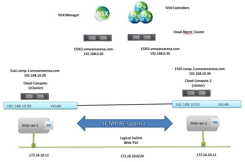
The NSX controller is a user space VM that is deployed by the NSX manager. It is one of the core components of NSX and could be termed as the “distributed hive mind” of NSX. It provides a control plane to distribute network information to hosts. To achieve a high level of resiliency the NSX Controller is clustered for scale out and HA.
The NSX controller holds three primary tables. These are a MAC address table, ARP table and a VTEP table. These tables collate VM and host information together for each three tables and replicate this throughout the NSX domain. The benefit of such action is to enable multi-cast free VXLAN on the underlay. Previous versions of vCNS and other VXLAN enabled solutions required multicast enabled on the Top of Rack Switches or the entire physical fabric. This provided a significant administrative overhead and removing this alleviates a lot of complexity.
By maintaining these tables an additional benefit is ARP suppression. ARP suppression will allow for the reduction in ARP requests throughout the environment. This is important when layer two segments stretch across various L3 domains. If a segment requests the IP of a MAC address that isn’t on a local segment the host will have the replicated information in its tables pushed to it by the controller.
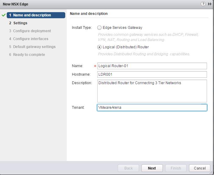
NSX Controller Deployment
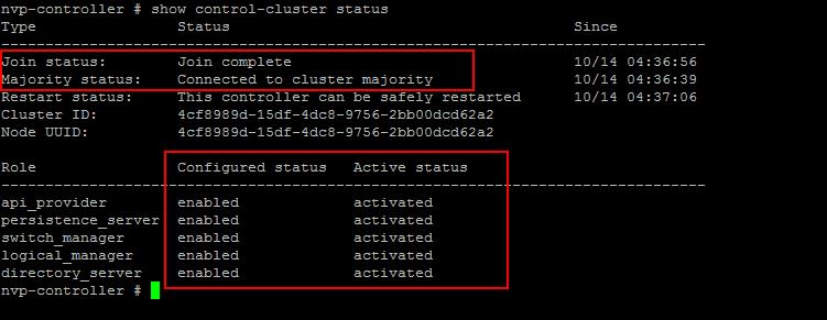
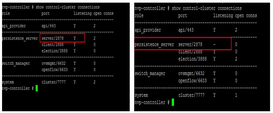
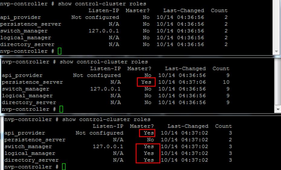
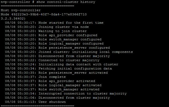
NSX Controllers are the control-plane of the solution. Deployed in a three-node cluster. these virtual appliances provide, maintain and update the state of all network function within the NSX domain. Built upon clustering technology such as Zookeeper, NSX can take failure well. Clusters can break, destroy or cease working and there will be no impact to an NSX domain as long as 1 instance is running. This is due to the slicing of information across the node cluster of network state information.
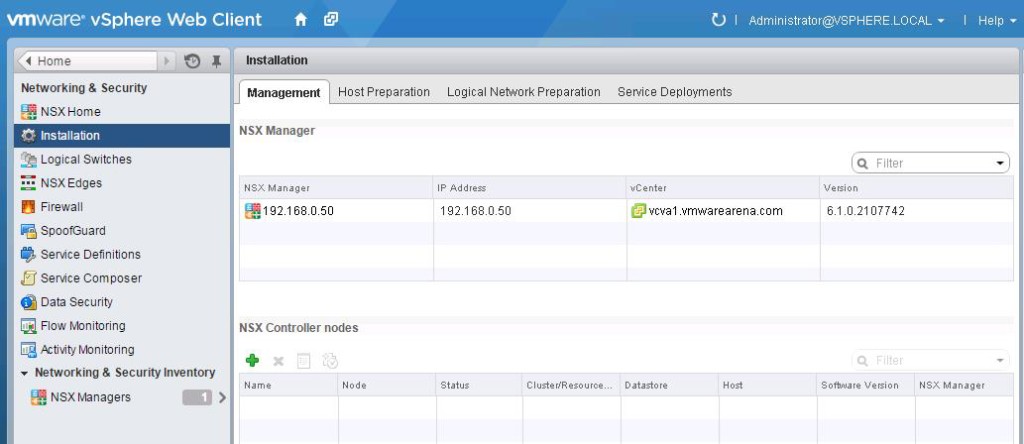
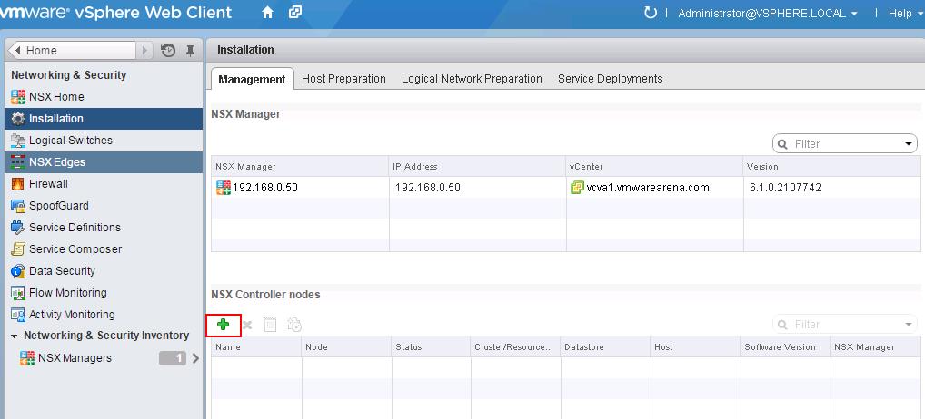
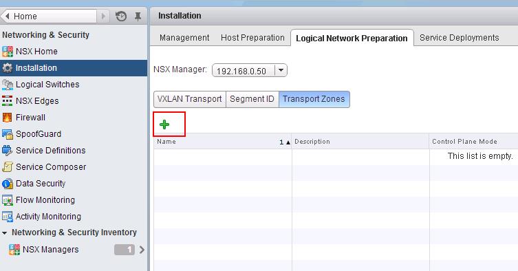
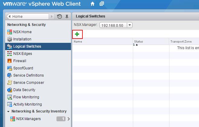
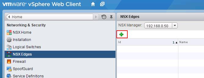
Click on + symbol under NSX controller nodes to deploy the first NSX controller node. It is always recommended to deploy the controllers in Odd numbers ( 3 ,5,etc). It provides redundancy incase of failure of other NSX controller.
![NSX Controller Deployment-1]()
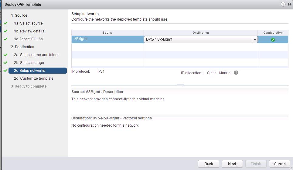
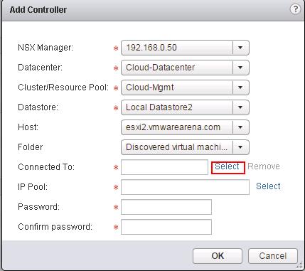
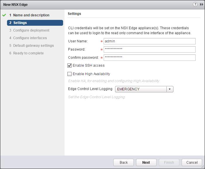
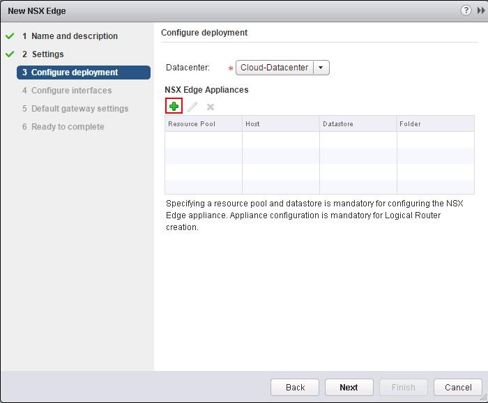
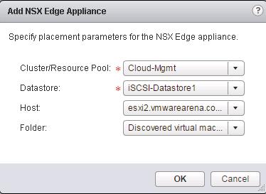
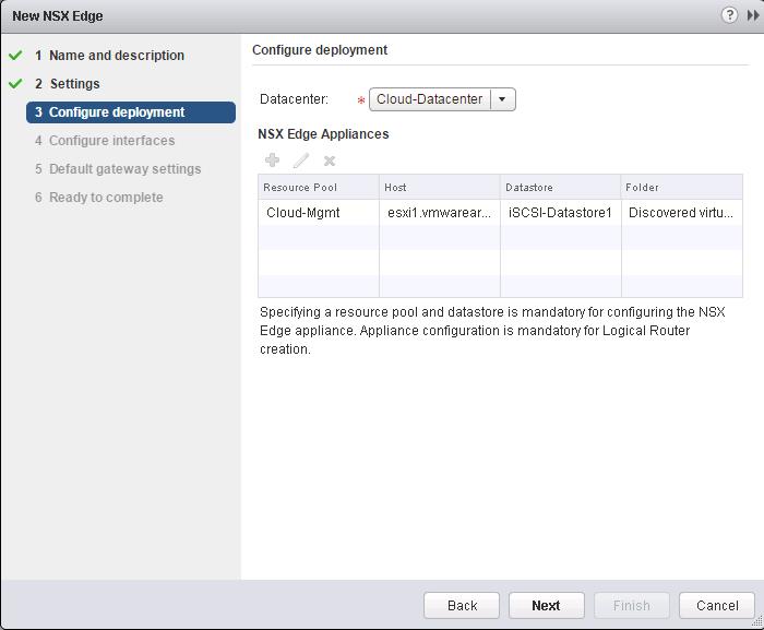
Select the options like NSX Manager, Datacenter, Cluster, Datastore, Host and Portgroup to deploy the NSX Controller. Click on Select option for “Connect To” to select the PortGroup.
![NSX Controller Deployment-2]()
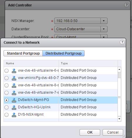
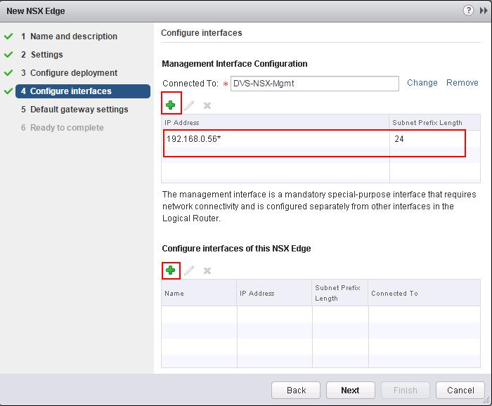
Select the Distributed Portgroup to connect to the Controller VM and Click on Ok.
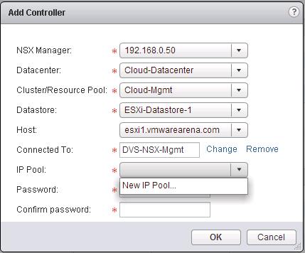
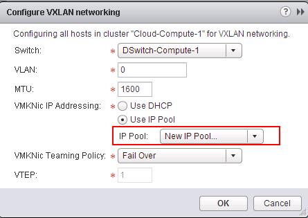
![NSX Controller Deployment-3]() Select New IP Pool from the IP Pool drop-down menu to open the Add IP Pool dialog box and configure the options.
Select New IP Pool from the IP Pool drop-down menu to open the Add IP Pool dialog box and configure the options.
![NSX Controller Deployment-4]()
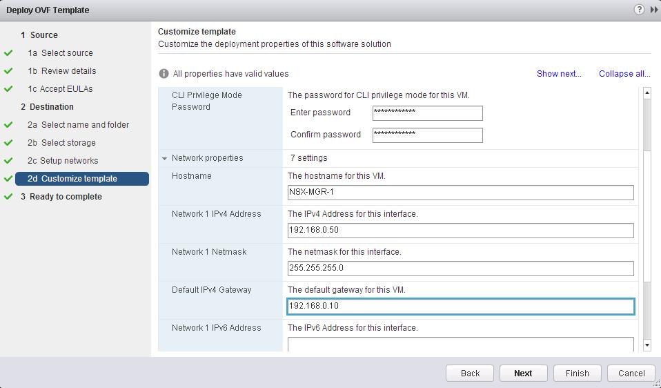
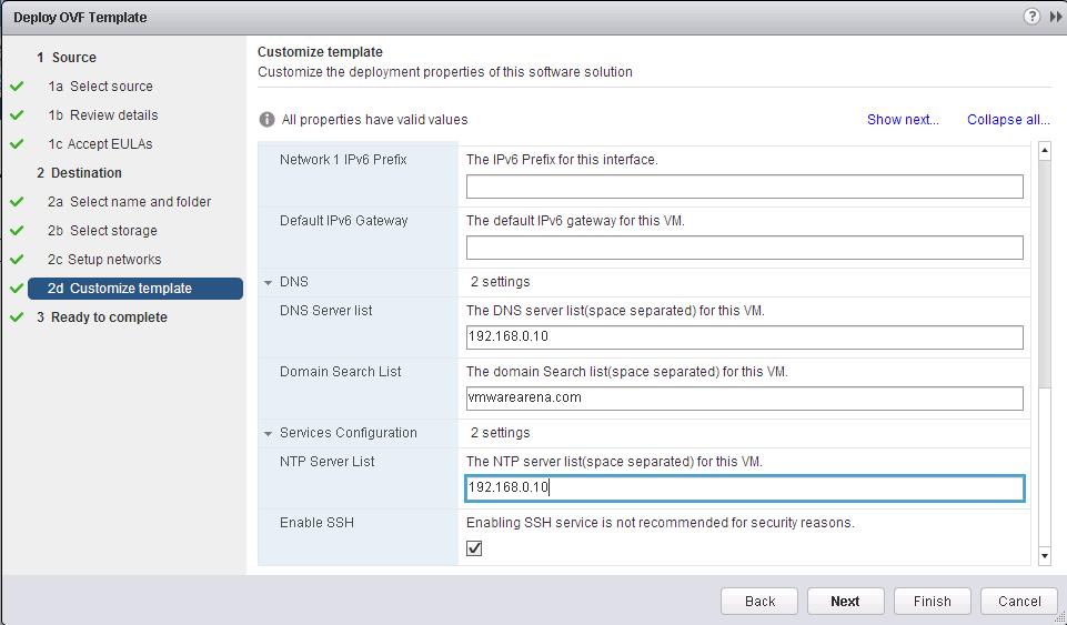
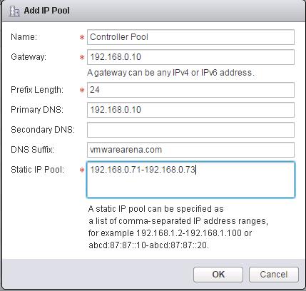
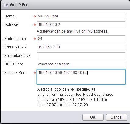
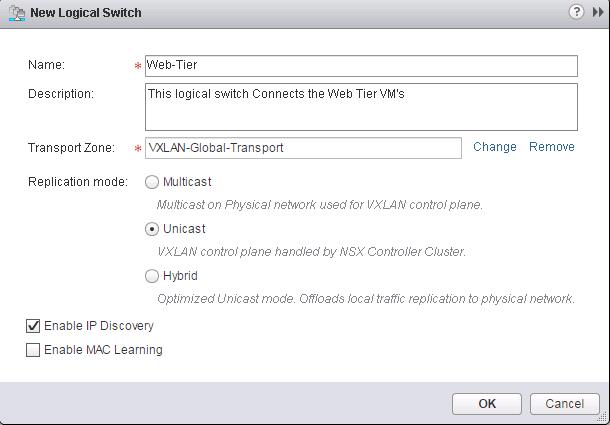
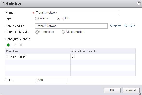
Specify the Name for the IP Pool, Gateway, Prefix length, Primary DNS, Secondary DNS, DNS Suffix and Static IP Pool for the Controller IP Pool. NSX Controllers will be using the IP address from this static IP Pool range during the deployment.
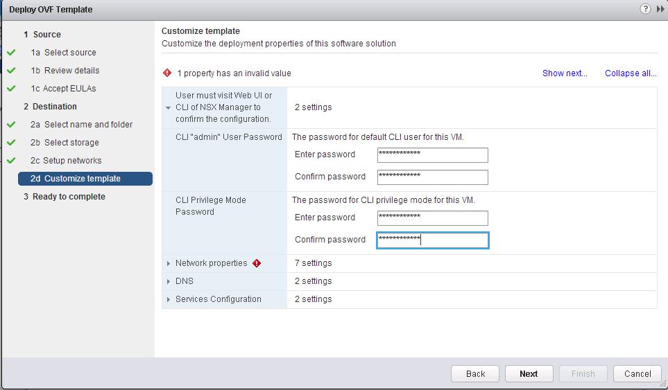
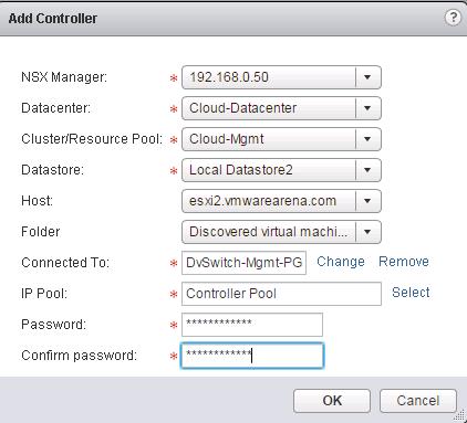
![NSX Controller Deployment-5]() Enter the Password for the Controller VM administrative account and Click on OK to deploy the first Controller Node.
Enter the Password for the Controller VM administrative account and Click on OK to deploy the first Controller Node.
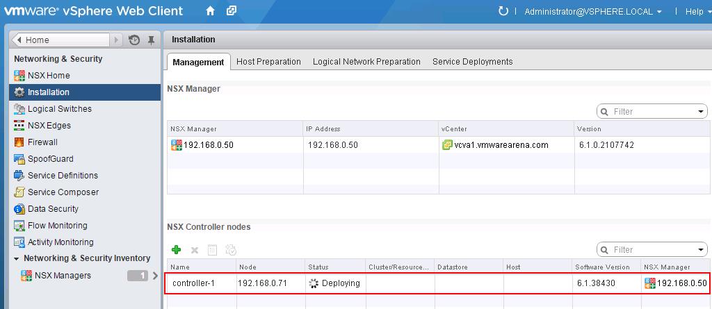
![NSX Controller Deployment-6]() You will be able to see the status of the NSX Controller Node under NSX Controller nodes.
You will be able to see the status of the NSX Controller Node under NSX Controller nodes.
![NSX Controller Deployment-7]()
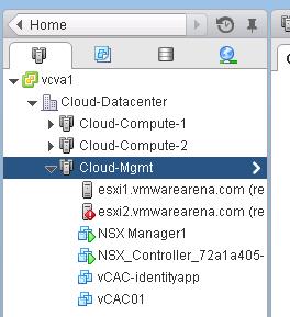
Once the deployment Starts, You will be able the See the Controller VM starting Name “NSX_Controller_XXXXXXX”.
![NSX Controller Deployment-8]()
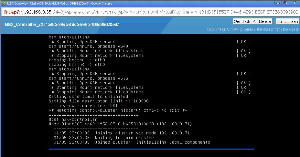
Open the Console of the NSX Controller VM to see the status of the boot up process. Wait untill the booting and customization of NSX controller. It assigns the IP related settings from the assigned IP Pool and configured Controller deployment options.
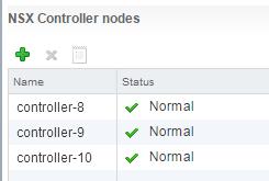
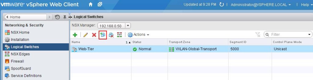
![NSX Controller Deployment-9]() Once Boot up of NSX Controller is completed. You can see the status of the NSX Controller turned to be “Normal”. Deploy the 2nd Controller once the First Controller status turned to be “Normal”.Follow the Same procedure to deploy the additional NSX Controllers. I have deployed 3 controllers for my environment.
Once Boot up of NSX Controller is completed. You can see the status of the NSX Controller turned to be “Normal”. Deploy the 2nd Controller once the First Controller status turned to be “Normal”.Follow the Same procedure to deploy the additional NSX Controllers. I have deployed 3 controllers for my environment.
Note – You will notice my controllers are not 1,2, &, 3. That is because my controllers deployment got failed because of some misconfiguration on IP Pools. After 7 failed deployment, I fixed the issue and later my controller deployment got success. That’s why you can see my controller name as 8,9 & 10.
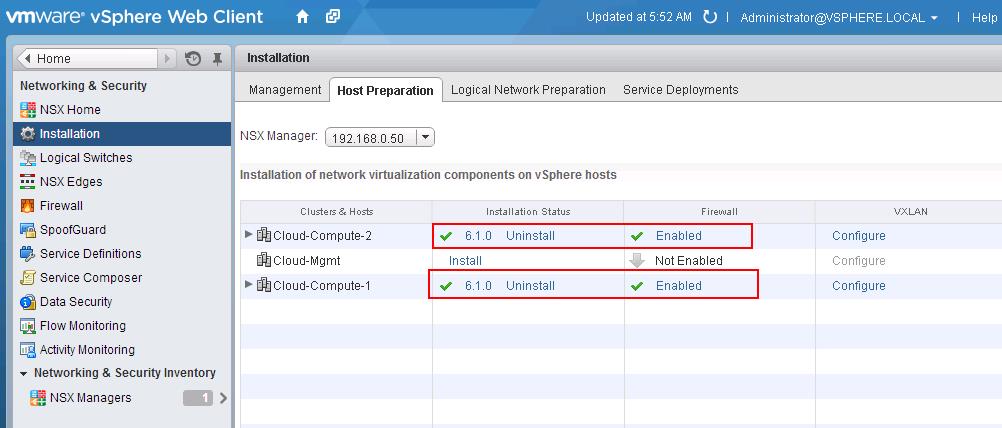
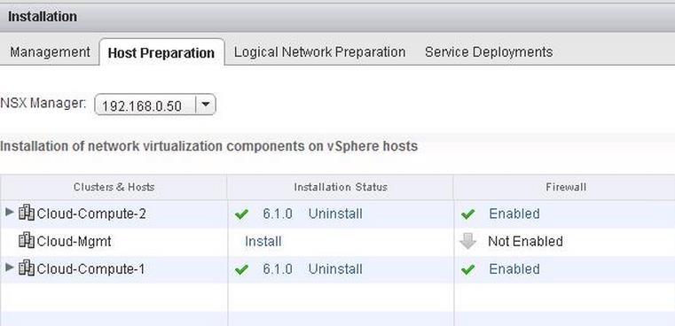
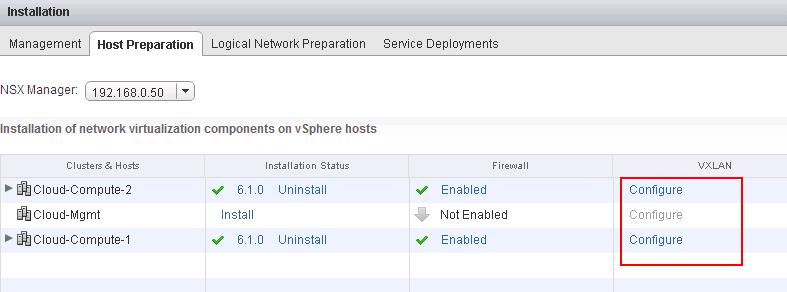
![NSX Controller Deployment-10]() With the NSX manager installed and controllers deployed, we have a management plane and control plane established. We are ready for the Host preparation. I hope this is informative for you. Thanks for Reading!!!. Be Social and share it in social media, if you feel worth sharing it.
With the NSX manager installed and controllers deployed, we have a management plane and control plane established. We are ready for the Host preparation. I hope this is informative for you. Thanks for Reading!!!. Be Social and share it in social media, if you feel worth sharing it.
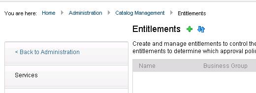
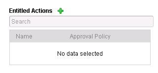
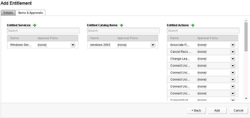
 Add the entitled service, Catalog items and Actions for this entitlement.
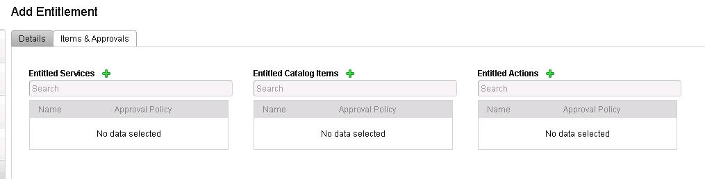
 Select the Machine from the Type and Select the Actions for the entitlements.
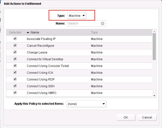
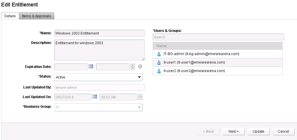
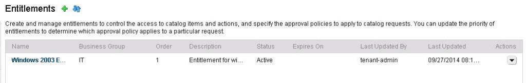 That’s it. Entitlement is created. We need to create and manage entitlements to control access to catalog items and actions. We will take a look at VM provisioning request in upcoming posts. I hope this is informative for you. Thanks for Reading!!!. Be Social and Share it in social media, if you feel worth sharing it.